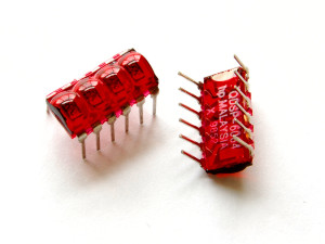
Around March of 2014, out of the blue, SparkFun started selling these beauties.
Those are 4-digit 7-segment LED displays in a DIP6 package. Tinkerers and enthusiasts everywhere let out a collective shriek of delight, throwing fistfuls of money at SparkFun, depleting their initial stock in less than half an hour. One early commenter summed up the feeling perfectly: “No idea what I’ll use it for, but don’t care: shut up and take my money!”
After a couple of weeks, I was finally able to buy some for myself.
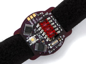
My first official project incorporating this component is what I’ve been calling the Bubble Clock Watch. It draws inspiration from SparkFun’s BigTime Watch kit, but it is meant to be smaller, and is based around the surface-mount TSSOP MSP430 instead of the through-hole DIP Atmega328.
The Design
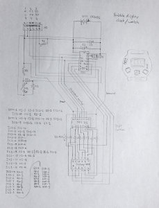
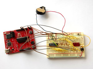
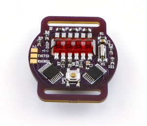
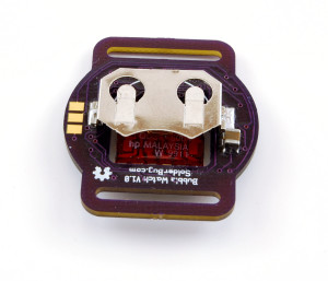
The design incorporates one MSP430g2231 microcontroller with an external 32kHz crystal, along with one surface-mount 74HC595 output shift register to drive the display. The clock is powered by a single CR2032 battery, and should last at least 5 years on the same battery if the time is viewed a few times a day.
SparkFun’s BigTime Watch displays the time for two full seconds after the button is pressed. With my design, I decided instead to show the time for only as long as the button is pressed. This allows the user to illuminate the display for only as long as needed to read the time. This will help extend the battery life.
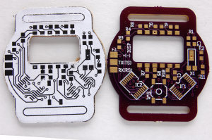
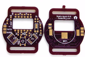
This is my third project to use Osh Park’s excellent PCB service. The board outline is as small as the outline of a regular watch, with slots routed out on either end to allow a strap to pass through. This is meant to be a wristwatch.
To allow a slim profile, I defined a cutout in the PCB to fit the bubble display. I bent the display’s pins outward until they were horizontal, and trimmed the pins down to a reasonable length that would cover the solder pads but not go beyond them.
I included a footprint for an optional capacitor to serve as a backup power source. There is enough charge in the capacitor to keep the clock running while changing the battery.
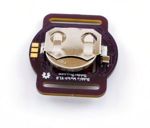
Underneath the battery, I defined a large pad to contact the negative terminal. When soldering it together, I added a blob of solder and pushed it around the pad until the whole pad had solder, and then added enough to create a sort of “pillow” that was raised enough to press against the battery.
This design features a programming interface made of a 2-layer edge connector with 0.1 inch spacing, similar to an ISA card edge connector. I connect to it using a 6-pin card socket that I harvested from some computer circuit boards. I have used this programming interface design successfully on a couple of previous projects.
The Result
When the battery is first put in, the clock starts at 12:00. To view the time, push the button. The display stays lit for as long as the button is held down.
To set the hours, hold down the button for 10 seconds, until the decimal point under the hours turns on. The hours increment each time the button is pressed and released. Next, to set the minutes, hold down the button for three seconds, and the decimal point will re-locate to under the minutes. Like the hours, the minutes increment each time the button is pressed and released. Also, the seconds are set to zero each time the minutes are incremented. To exit set mode, hold the button down for three more seconds, and the display turns off.
Unfortunately, I found that the watch is susceptible to ESD. So far, the microcontroller hasn’t been fried, only reset multiple times. A discharge usually happens when pulling a shirt sleeve over the watch, as happens when putting on or taking off a shirt, and results in the clock resetting itself to 12:00.
There is no ground plane in the PCB, so maybe that would be something I could improve in a later version.
| Component | QTY | Source |
|---|---|---|
| 100 Ohm Resistor | 8 | SMD 0805 Resistor and Capacitor Book (Adafruit) |
| 10 K Resistor | 2 | SMD 0805 Resistor and Capacitor Book (Adafruit) |
| 100 K Resistor | 1 | SMD 0805 Resistor and Capacitor Book (Adafruit) |
| 0.1 µF Capacitor | 2 | SMD 0805 Resistor and Capacitor Book (Adafruit) |
| 1 µF Capacitor (optional, approx. 3.3mm x 2.6mm) | 1 | salvaged from old circuit board |
| SMD Pushbutton | 1 | SparkFun |
| MSP430g2231 TSSOP-14 | 1 | Element14 |
| 74VHC595 Serial-in Parallel-out shift register | 1 | Element14 |
| Bubble Display – 7-segment (4-digit) | 1 | SparkFun |
| 32.768 kHz SMD Watch Crystal | 1 | Element14 |
| CR2032 3V Coin Cell | 1 | convenience store |
| SMD Battery Clip for CR2032 | 1 | SparkFun |
| Designator | Component |
|---|---|
| R1 | 100 K Resistor |
| R2 | 10 K Resistor |
| R3-R10 | 100 Ohm Resistor |
| R11 | 10 K Resistor |
| C1, C2 | 0.1 µF Capacitor |
| C3 | 1 µF Capacitor (optional) |
| DISP | LED Bubble Display |
| H1 | programming header (not a physical component) |
| IC1 | MSP430g2231 |
| IC2 | 74VHC595 |
| SW1 | SMD Pushbutton |
| X1 | Crystal |
This is open hardware. You can download an archive containing the source code, BOM, gEDA PCB layout file, Gerbers, and netlist.
Awesome project! I purchased the bubble displays without knowing what to do with them. I’d very much like to build your watch but I don’t know how to program the MCU. I have some limited experience with programming the ATmega (Arduino) and PICAXE MCU’s. DigiKey charges a $50 set up fee for programming, which for a non-commercial hobbyist like me, is unreasonable. I’d appreciate it if you could give me detailed advice on how to program the MCU, or better yet, I could construct it and send it to you for programming. Thanks!
Thanks! I program my MCUs using the MSP430 LaunchPad (http://www.ti.com/tool/MSP-EXP430G2). I use TI Code Composer Studio (http://www.ti.com/tool/CCSTUDIO) (based on Eclipse) which is free, and connect to the LaunchPad using USB.
The current version of the LaunchPad comes with a couple of 20-pin DIP chips, the MSP430g2452 and MSP430gg2553. I got my first one back when the supplied chips were the 14-pin MSP430g2211 and MSP430g2231. The current LaunchPad is still compatible with the g2231 chip.
My hardware setup for programming consists of jumper wires from the LaunchPad connecting to a very small (6-pin, 3 pins front and back) ISA-style connector. The pads on the side of the watch PCB are the programming pads, spaced at 0.1″, which is the right spacing for the connector. The PCB fits directly into the connector slot, with power, ground, transmit, receive, test, and reset all available. It’s less fancy than pogo pins, but it provides a firm connection and it gets the job done.
Before I burn anything up, I’d like to clarify watch pads correspond to which pins on the MSP430 LaunchPad.
Pads on top of watch PCB (from top to bottom)
PAD 1 + = pin 1 on 2231 = VCC on MSP430
PAD 2 TS = pin 11 on 2231 = TEST on MSP430
PAD 3 RS = pin 10 on 2231 = RST on MSP430
Pads on bottom of watch PCB (from top to bottom)
PAD 1 – = pin 14 on 2231 = GND on MSP430
PAD 2 TX = pin 3 on 2231 = P1.1 on MSP430
PAD 3 RX = pin 4 on 2231 = P1.2 on MSP430
Does this appear to be correct? Thanks.
Pads on top of PCB from top to bottom:
1. VCC
2. TX
3. RX
Pads on bottom of PCB from top to bottom:
1. GND
2. TS
3. RS
The naming scheme for the pins on the silkscreen is:
pad on side facing you (pad on back side)
Thanks. I was sleep deprived when I wrote that.
Pads on top of bubble watch PCB
PAD 1 + = pin 1 on 2231 = VCC on MSP430
PAD 2 TX = pin 3 on 2231 = P1.1 on MSP430
PAD 3 RX = pin 4 on 2231 = P1.2 on MSP430
Pads on bottom of watch PCB
PAD 1 – = pin 14 on 2231 = GND on MSP430
PAD 2 TS = pin 11 on 2231 = TEST on MSP430
PAD 3 RS = pin 10 on 2231 = RST on MSP430
I’ve ordered the boards and parts. Now we wait…
Hi there, I don’t see any mention around the PCB… does anyone knows where to buy it?
I bought the PCBs from OSH Park. https://oshpark.com/
To buy ones for yourself, download the archive at the bottom of the post (above), unzip the archive, and find the folder named “gerbers”. Make a zip of that folder and its contents, and upload it to OSH Park using the “Let’s Get Started” tool on their homepage.